You’ve got a dispersion grade, a particle size histogram, and a set of microscope images on your desk—now what decision should you actually make? For many laboratories and production teams, receiving a test report is only the beginning of the challenge. Knowing how to interpret carbon black dispersion results correctly is what turns testing from a routine checkbox into a real tool for quality control and process improvement. At GT-TEST, a professional laboratory testing equipment supplier serving plastic pipe and polymer material industries worldwide, we regularly help customers move from “having data” to “using data” with confidence.
The Three Outputs That Matter Most
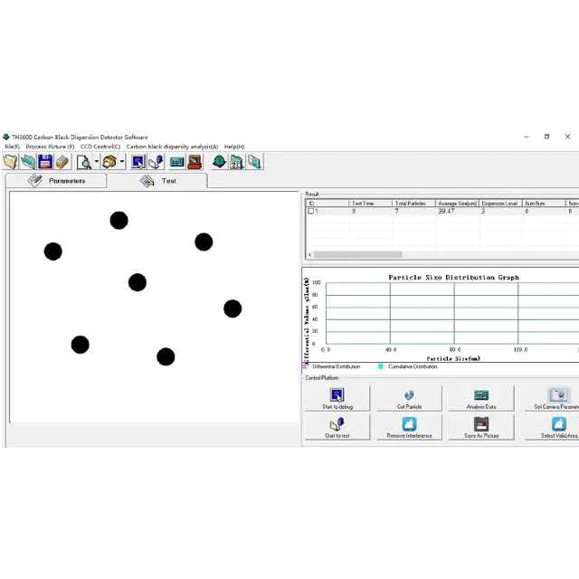
A carbon black dispersion test typically produces more information than a single pass or fail result. Understanding how the main outputs work together is the foundation of correct interpretation.
Dispersion Grade: What It Actually Summarizes
The dispersion grade is designed to give a simplified overview of dispersion quality. It compresses complex image analysis data into a standardized rating that can be compared against specifications or internal criteria. This makes it useful for quick decisions, such as batch release or rejection.
However, the grade does not tell the full story on its own. It summarizes overall dispersion behavior across the analyzed fields of view, but it does not explain why a sample achieved that grade. Treating the grade as the only meaningful result often leads to missed warning signs.
Particle Size Distribution: How to Read Shifts
The particle size distribution provides deeper insight. Instead of a single number, it shows how carbon black particles and agglomerates are distributed by size. Shifts in this distribution reveal changes in mixing effectiveness and process stability.
For example, a distribution dominated by small particles usually indicates effective dispersion. A tail extending toward larger sizes suggests agglomeration. Comparing distributions over time can reveal gradual process drift long before grades cross rejection thresholds.
Saved Images: What to Document and Why
Images are the most underestimated output of dispersion testing. They provide direct visual evidence of the material’s internal structure. Saved images allow teams to revisit results, explain decisions to non-technical stakeholders, and defend conclusions during audits or customer disputes.
Images also help bridge the gap between numerical data and real material behavior. When a histogram shows an unexpected shift, images often reveal the underlying cause.
What “Good” and “Bad” Often Look Like
Knowing how dispersion defects appear in practice helps translate test outputs into meaningful conclusions.
Few Large Agglomerates vs. Many Small Ones
Not all dispersion problems are equal. A small number of very large agglomerates often points to insufficient shear during mixing. These large clusters act as strong stress concentrators and can dominate failure behavior.
In contrast, many smaller agglomerates may indicate marginal dispersion conditions or inconsistent processing. While each individual cluster may seem less severe, their cumulative effect can still compromise long-term performance. Understanding which pattern you are seeing helps identify the most likely root cause.
Spotting Windows and Streaks
Windows are regions where carbon black concentration is locally reduced. Streaks indicate uneven distribution along the flow direction. Both are considered high-risk features because they create weak zones within the polymer.
These defects are especially critical in applications like PE pipes, where uniform UV protection and mechanical integrity are essential. Even if the dispersion grade appears acceptable, the presence of windows or streaks should trigger closer investigation.
Common Interpretation Mistakes
Misinterpreting dispersion results is surprisingly easy, even for experienced teams. Avoiding common mistakes is key to making reliable decisions.
Treating One Image as the Whole Sample
A single microscope image rarely represents the entire sample. Dispersion can vary across different regions, especially in extruded products. Drawing conclusions from one or two images increases the risk of bias.
Proper interpretation requires reviewing multiple fields of view selected according to a defined method. This approach reduces the chance that results reflect a localized anomaly rather than the overall material condition.
Comparing Results Across Different Preparation Methods
Comparing dispersion results obtained using different specimen preparation methods or magnifications is another frequent error. Changes in slice thickness, surface quality, or optical settings can significantly influence results.
Without consistent preparation and analysis conditions, differences in results may reflect method variation rather than true changes in dispersion quality. This makes trend analysis unreliable and undermines confidence in decisions.
Linking Results to Mixing and Processing
Dispersion results are most valuable when they are connected to process conditions rather than viewed in isolation.
Signs of Insufficient Shear vs. Over-Processing
Certain dispersion patterns are strongly associated with specific processing issues. Large agglomerates often indicate insufficient shear, low mixing energy, or reduced residence time. On the other hand, extremely fine dispersion accompanied by material degradation may suggest over-processing.
Recognizing these patterns allows engineers to adjust screw design, mixing speed, or temperature settings in a targeted way instead of relying on trial and error.
Validating Improvement After Process Changes
After making process adjustments, dispersion testing provides a way to validate improvement objectively. Comparing particle size distributions and images before and after changes confirms whether modifications had the intended effect.
This feedback loop transforms dispersion testing into a proactive process control tool rather than a reactive quality check.
Using Standards to Set Acceptance Criteria
Standards provide an external reference that helps laboratories define clear acceptance rules.
ISO 4427 and Dispersion Grade Requirements
In applications such as PE piping systems, ISO 4427 links carbon black content requirements with dispersion grade expectations. This reflects the understanding that both quantity and distribution influence long-term performance.
Interpreting dispersion results within this framework ensures that acceptance decisions align with recognized industry requirements rather than subjective judgment.
Defining Pass or Fail Before Testing
One of the most effective ways to avoid biased interpretation is to define pass or fail criteria before testing begins. When acceptance thresholds are established in advance, results are evaluated consistently, and the temptation to reinterpret borderline data is reduced.
Clear criteria also make communication with customers and auditors more straightforward, as decisions are based on predefined rules rather than post-test debate.
Building a Decision-Ready Report for Customers
A well-structured report turns dispersion data into a tool for communication and trust-building.
Information That Should Always Be Included
A decision-ready report includes clear sample identification, test method details, operator information, and date and time of testing. These details ensure traceability and make results easier to verify and reproduce.
Including this information consistently also signals professionalism and strengthens customer confidence in the testing process.
Presenting Data for Non-Technical Stakeholders
Not all report readers are dispersion experts. Presenting results in a clear, visual way helps non-technical stakeholders understand what the data means.
Graphs, representative images, and concise summaries make reports more accessible and reduce misinterpretation. This is especially important when results are shared with procurement teams or management rather than laboratory specialists.
Result Patterns, Likely Meanings, and Next Actions
Result Pattern | Likely Meaning | Next Action |
High grade with many large particles | Agglomeration due to insufficient mixing | Review mixing shear and dispersion stage |
Acceptable grade but windows visible | Local carbon-black-poor zones | Check compounding uniformity and material feed |
Different results between laboratories | Method or preparation mismatch | Align preparation method and magnification |
Why Interpretation Is as Important as Measurement
Dispersion testing does not prevent defects by itself. Interpretation is what converts measurement into prevention. Without proper interpretation, even accurate data can lead to incorrect decisions.
At GT-TEST, we emphasize complete workflows that combine standardized specimen preparation, automated analysis, and clear reporting. This approach ensures that dispersion results are not only accurate but also meaningful and actionable.
By integrating these elements, laboratories can reduce uncertainty, respond faster to issues, and provide stronger evidence of quality control to customers and regulators.
Conclusion
Numbers alone do not protect products; understanding does. Correctly reading grades, distributions, and images is what turns testing into real quality assurance. When teams learn to connect dispersion data to processing behavior and standards, testing becomes a powerful preventive tool rather than a reactive one. Mastering carbon black dispersion data interpretation helps manufacturers reduce risk, improve consistency, and defend quality decisions with confidence. As a professional supplier of polymer and plastic pipe testing equipment, GT-TEST supports laboratories with standardized preparation tools and automated reporting systems designed to make interpretation clearer and more reliable. If you want to strengthen your dispersion testing workflow and turn results into confident decisions, contact us to learn more about our solutions.
FAQ
What is the most important output in a dispersion test report?
All outputs matter, but dispersion grade, particle size distribution, and saved images together provide the most complete understanding.
Can a good dispersion grade still hide problems?
Yes. Windows or streaks visible in images can indicate risk even when the overall grade appears acceptable.
Why do different labs sometimes report different dispersion results?
Differences often come from inconsistent preparation methods, magnification settings, or field-of-view selection rather than true material variation.
How can dispersion results support process improvement?
By linking result patterns to mixing and processing parameters, dispersion testing helps identify specific adjustments that improve material quality.


